
Wastewater Treatment Facility
Overview
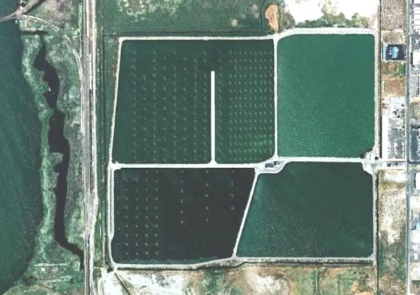
The District wastewater facility consists of a 130 acre facultative lagoon system and was originally built in the late 1950's and has had several minor improvements prior to 2001. In 2001, the facility added major upgrades in the pumping, screening, and aeration systems.
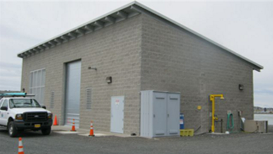
Influent Pump Station
Due to the lower elevation of the District collection system, incoming wastewater must be raised to the elevation of the treatment facility. The influent pump station performs this task.

The influent pump station incorporates a trench-type self-cleaning wet well and is equipped with four 75-horsepower (hp), 2,550-gallon-per-minute (gpm) submersible pumps. The station has a current firm capacity of 11 million gallons per day (mgd). The structure is sized to accommodate an ultimate peak flow of 30 mgd.
The station’s control system incorporates a programmable logic controller (PLC), ultrasonic level sensors, and variable frequency drives (VFD). The program logic automatically varies pump speed and number in service to maintain operator-selected wet well level set-points. Influent flow rate is measured with a 14-inch-diameter magnetic flow meter. Flow information is transmitted to the plant computer. An 18-inch-diameter force main conveys wastewater from the pump station to the screen building.
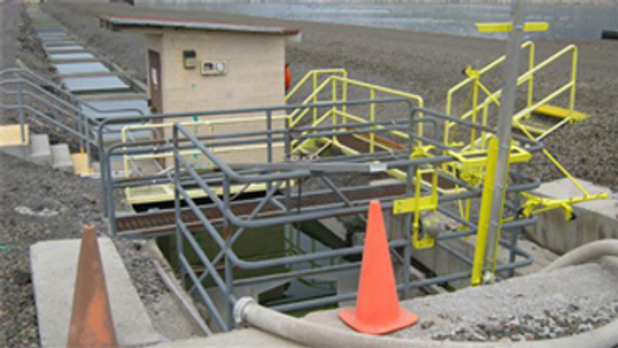
Screening System
Before the wastewater can enter the treatment ponds, the large particles rags in the wastwater must be removed by a screen.
The screen building is located in the widened levee area at the center of the four ponds. The system consists of a 4-foot-wide mechanically raked bar screen, a screenings washer/compactor, and a bypass channel. In its current configuration, the screen can accommodate a peak flow of 21 mgd. The washer/compactor deposits the screenings into a dumpster.

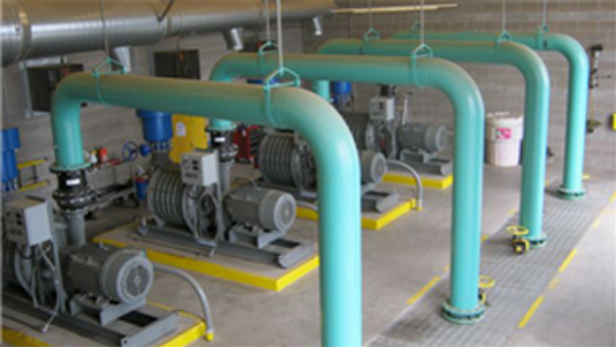
Mechanical Aeration
Aerobic organisms in the treatment ponds require oxygen to perform treatment. In order to increase performance of those organisms, dissolved oxygen is added to the treatment ponds through aeration blowers. Aeration blowers can be thought of as large compressors.
Four 2,300-standard-cubic-foot-per-minute (scfm), 150-hp multistage centrifugal blowers were installed in 2005 to replace the troubled rotary screw blowers that were originally housed in the blower building. The Aeration blowers are the largest energy consumers in the entire treatment system.
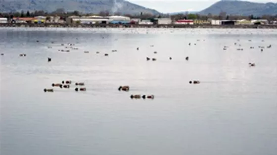
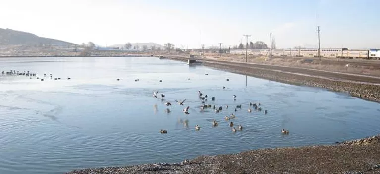
Treatment Ponds
The treatment ponds provide the biological treatment and the treatment facility primarily through aerobic and facultative organisms.
The four ponds were a part of the original treatment plant construction project and have a combined surface area of 130 acres. Currently, Ponds # 1 and #2, the smallest and the shallowest, are not an integral part of the treatment scheme. Their primary function is storage and equalization. Ponds #1 and #2 have a combined storage capacity of 71 million gallons.
Ponds #3 and #4 have a combined surface area of 75 acres and a capacity of 176 million gallons and are equipped with vertical tube aerators. Screened wastewater enters Pond #4 and flows into Pond #3. To improve flow conditions, Pond #4 is divided into two zones by an earthen levee. Pond #3 is equipped with a membrane baffle wall which routes pond effluent along its south levee.
The aerators in Pond #4 are designed to provide the air necessary for aerobic treatment of the wastewater. The primary function of the aerators in Pond #3 are to prevent ice buildup on the pond surface during cold weather. Air from the aeration blowers is routed through a ductile iron pipe buried in the levee which separates Ponds #3 and #4. PVC lateral pipes resting on the pond floors feed air to the individual aerators. Outlet structures allow effluent to be withdrawn from either Pond #3 or Pond #4.


Disinfection
Disinfection is used to eliminate pathogenic bacteria prior to allowing the treated wastewater into the Klamath River.
Chlorine gas is used for effluent disinfection. The gas is injected into carrier water to create a chlorine solution which, in turn, is injected into the pond effluent. Contact time is provided by a single 650-foot-long chlorine contact channel. Recently District staff has constructed a sluice gate mixing system that provides good initial mixing of the applied chlorine and the treated wastewater. District Staff have also recently designed and built a custom apparatus that provides a non-entry hydraulic cleaning to the tank.
Effluent Outfall
Following disinfection, the effluent passes over a flow measurement weir into drainage ditch. In the ditch storm water from both the County and the city are mixed with the District wastewater effluent. Vertical turbine pumps convey the effluent and runoff to wetlands, which as contiguous to the Klamath River.


Regulatory
Treated effluent form the District wastewater facility is regulated by the Oregon Department of Environmental Quality or (DEQ). The District has an NPDES Permit that provides the effluent criteria that must be met by the District in order to discharge treated effluent to the Klamath River.